East mudsill replacement:

Back to the seismic upgrade and foundation repair…

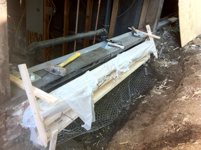
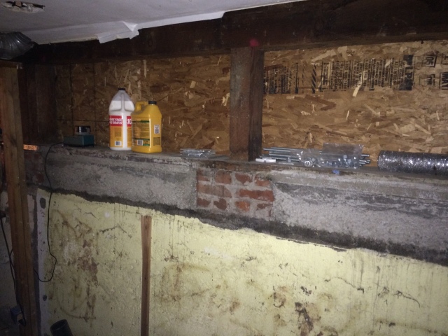
I was getting ready to tie the south and east sides of the foundation wall together with rebar when I noticed that the eastern mudsill had some weird dents in it. Closer inspection revealed that the sill was so badly dry-rotted that its structural strength fell somewhere between crusty bread and balsa wood. It looks like there might have been some leakage from the soil stack or possibly from condensation dripping from the fresh water pipes above it. I’ll address both of these after I replace the sill.

It would be nice to replace the whole sill in one or two large pieces but in this case I don’t think that is going to be possible. I would have to shore up the whole side of the house and my three jacks are currently in use on the south side. My strategy will be to replace the sill in four pieces and then link the pieces together with steel strap-ties. This solution will be cheap, strong, effective and code compliant.

I still need to figure out which jack I can use for this.

Our rotted east side mudsill.

Our rotted east side mudsill.

Posted in Uncategorized | Leave a comment

Interlude: A boom in the night.

Our furnace is a gas fired Carrier 58GS100 from way back in 1975. During the colder days in fall we had been mostly relying on electric heat to keep us warm upstairs. However, since the house needed to stay warm enough to keep the pipes from freezing, we set the thermostat to come on at 50F. As the temperature has been dropping we have been startled to hear an occasional explosion in the basement, sounding kind of like something really heavy falling over. It was time to go down and have a look.

First a little about my philosophy of repairing furnaces…

With rare exception, HVAC guys are probably the most anti-DIY of all of the trades. Don’t bother looking for repair help on HVAC forums because they won’t give you any. If you suggest fixing your furnace yourself, they will try to convince you that the very act of opening your furnace is inviting certain death. Plumbers will occasionally have a side business doing HVAC and the HVAC people have a very dim view of this as well. Their view is that only a fully licensed HVAC service technician is capable of protecting you from the death machine in your basement. In my opinion, these are nothing but the signs of a trade attempting desperately to construct barriers to entry.

I remember one time I was called to take a look at a furnace that was giving off a hydrocarbon odor. The homeowner had previously called a furnace repair man and he told her with absolute certainly that the furnace required replacement immediately and she was courting death to even turn it on. I had a look for her and found that an eight-inch diameter hole on the chimney was allowing flue gases to escape into the basement. There is no way on earth that the repairman did not see it. Did he tell her this? Of course not. Cost of parts to fix: $15.

Using this kind of doom and gloom scenario as a sales technique is ubiquitous in the HVAC repair industry. I’ll be the first to admit that carbon monoxide is dangerous. However, due to the failsafes built into every furnace, it is really difficult to get a furnace to fail this way. The minuscule danger that still exists is ameliorated by the use of a cheap carbon monoxide detector (We are using two). My feeling is that if you understand the concepts involved in servicing a four-stroke internal combustion engine, and are willing to take sensible precautions then you probably have the required background to attempt a furnace diagnosis. The concept of igniting a proper air-fuel mixture is shared between the two and I would suggest that fixing an automobile is actually both more difficult and more dangerous. Anyway, back to work…

The problem we were experiencing is called delayed ignition. The furnace fills with a pocket of un-combusted gas and the sound comes from it igniting in a tiny explosion. (Keep your face away or you will lose your eyebrows.) The most common cause is that the burner has clogged with dirt or rust or whatever and needs to be cleaned. This was the case for us – our igniter was a bit clogged with junk as well. If you do this yourself, verify that the heat exchanger wall hasn’t rusted through.

Cleaning the igniter. A pile of rust was trapped next to the bimetallic strip, making it difficult to contact a momentary switch.

Cleaning the igniter. A pile of rust was trapped next to the bimetallic strip, making it difficult to contact a momentary switch.

Burners removed for cleaning with a wire brush.

Burners removed for cleaning with a wire brush.

The heat exchanger missing its burner. You get extra points for vacuuming out all the crap.

The heat exchanger missing its burner. You get extra points for vacuuming out all the junk at the bottom.

Posted in Uncategorized | Leave a comment

South side foundation crack repair:

We learned some interesting things while parging. This foundation was poured in three distinct layers and there was a significant amount of soil cave-in between pours. These mixed soil layers took quite some time to dig out. There was also no footer, which came as no surprise since I think this was an invention that had not yet gained widespread use when the house was built in 1908. Strangely, the rear southeast corner of the foundation was only a few inches thick in the bottom foot or so probably from a particularly bad soil cave-in soil during the pour. These two last things made the foundation much like a blade sitting in the soil and this helps explain why that corner of the house has sunk so much. There is also a big crack on the outside of the foundation that allowed the whole last ten feet or so of the foundation to hinge as it sunk into the earth.

The problem of a sunken house is rarely that it has sunk. Over the years homeowners alter to the house to accommodate changes in its geometry. The real problem is that if the house has sunk and the reason for sinking is not removed, the house will likely continue to sink. This being said, I decided to shore up the foundation on the southeast corner and mend the crack in a way that should last until the foundation is completely replaced in 100 years from now.

The fix:

1: Jack rear corner of the house and support it with needle beams.

2: Lift and support the section of sunken foundation wall with hydraulic jacks.

3: Dig under the foundation wall and pour mini-footer for the bad section of wall.

4: Tie the corner together with rebar.

5: Chip out and fill the two end cracks with hydraulic cement.

Progress:

The corner of the house is supported by a beam and three posts in order to take weight off the foundation wall.

The corner of the house is supported by a beam and three posts in order to take weight off the foundation wall so that I could dig under it for the footing.

Here you can see the sharp bottom edge on the south east corner of the foundation wall that has sunk so much over the years. The triangular block at the lower right is concrete that I have poured to keep the wall in place after jacking.

Here is the sharp bottom edge on the southeast corner of the foundation that has sunk so much over the years. The triangular block at the lower right is some of the concrete I poured to keep the wall in place after jacking. After the jack is removed, I will fill in the remaining gaps.

The next step will be to tie the corner together.

Posted in Uncategorized | Leave a comment

Foundation repair and waterproofing prep: north and south sides.

When we partially excavated the foundation on the north and south sides of the house to make room for forms, it was noted that some of the concrete was in pretty bad condition. How bad? It was crumbling to a depth of two to three inches in a few areas. Since the foundation was already partially uncovered it was decided that this was a good a time to repair things and waterproof a bit while we are at it. Working with three to four hired laborers each day, the excavation took four days.

The completed south side trench.

The completed south side trench. I covered both trenches with tarps to keep out the weather.

The patching involved in foundation repair is a bit like dentistry. Here are the steps: (Time estimate is for DIY part-time work, not 9-5.)

1: Clean the existing concrete of adhered and intercalated soil. (One day)

2: Remove any large protuberances from the external surface. (One day)

3: Tap over the entire surface with a hammer. Areas that are excessively weak will be obvious. Remove them with the hammer drill. (One day)

4: Use a wire brush to remove loose concrete. (Two days)

5: Wash the face of the concrete with water. (One day)

5: Seal any cracks found with hydraulic cement. (One day)

6: Working from the bottom up, “parge” the external surface of the foundation with topping mix. This creates a new hard surface to accept waterproofing. (One week+ depending on the condition of the foundation )

7: Apply waterproof membrane to surface and then backfill. (At least two days)

The parging process itself (#6 above) is probably the toughest step. Thoroughly mixing each 80-pound bag of topping mix and getting it down into the muddy trench is physically brutal and for all the effort you only get one cubic foot per bag, not much for a wall that is 25 feet long. At max only about four bags can be mixed and placed by hand per day; after that, I need a couple of days of rest. The man-hours for the physical labor and subsequent recovery create the largest time sink for waterproofing. If done correctly it creates a strong, adherent coating that should last another hundred years. If rushed, a weak, leaky coating will result.

IMG_3294

Removal of concrete ledge with a hammer drill. The concrete at that level was in good condition.

The wall after removal of the ledge and wire-brushing. Note the newly exposed aggregate.

The wall after removal of the ledge and wire-brushing. Note the newly exposed aggregate ready to accept the first coat of topping mix.

Posted in Uncategorized | Leave a comment

Foundation capping forms:

To create a load path from the foundation up through to the house, the gaps between the foundation and the mudsill must be filled with concrete. When concrete is added to the top of a foundation it is sometimes called foundation capping. The general strategy is to create forms on either side of the gap. On one side only, the form will have a one-inch gap at the top to allow concrete to be stuffed in. Does this make things more difficult? Yes, but it beats removing the mudsill to pour from the top.

Before building each form, I carefully attached some self-adhesive flashing tape to the underside of the sill. This functions as a kind of damp-proof barrier so that the mudsill doesn’t draw moisture from the concrete. Making each form takes about a day though some are more complex than others. I’m using 3/8” plywood as the face and 2×4 lumber to reinforce it. The form is secured with steel form wire that has been doubled over and wrapped once around the 17-inch bolts that I have epoxied into the foundation. To tighten the wire, the screwdriver is alternately pulled hard and twisted until tight. One must be careful; since you need to know when to stop tightening. Once the slack is taken up and the wire is just a bit too tight and the wire will snap. After both sides are wired to the bolts, I use some wood scraps to stabilize the form vertically. On my first attempt, I failed to reinforce the mudsill from deflecting vertically and the sill ended up slightly bowed after stuffing with concrete. The day before the concrete is poured the existing concrete should be thoroughly wetted. Old dry concrete will suck moisture from the new concrete at the interface and make it weaker.

IMG_3194

One concrete capping form. The plastic sticking out is to keep the concrete from sticking to the form. The chicken wire below is to repair some of the wall below.

After a week, the steel wire is snipped and the forms are removed. If the concrete surface is imperfect it can be filled in later with topping mix. As the concrete sets it shrinks a bit so I made sure to tighten the bolts again. The city plan calls for the bolts to be tight enough such that the square washer just starts to dent the wood of the sill.

The completed concrete on the west side of the house. The south side is now complete as well.

The completed concrete on the west side of the house looks really great. The south side is now complete as well. Both still need to be coated with topping mix and then painted to make them perfect.

Posted in Uncategorized | Leave a comment

Concrete removal: north and south sides:

Back to the seismic upgrade!

In order to create forms to fill the gaps between the foundation and the mudsill, I found it necessary to excavate down a couple of feet around the outside of the foundation. However, at some point in the past, someone thought it would be a good idea to pour a bunch of concrete next to the cripple wall on the outside of the house. This was no doubt done in order to stop the infiltration of soil and water through the previously mentioned foundation gap. A concrete slab for the garage abuts the north side of the house as well. To move forward with the project, it all must go.

I started with the intention of working thirty minutes or so per day. Why such a short time? Breaking concrete with a ten pound hammer is more difficult than it looks. The smart thing to do would have been to bring in a jackhammer and diamond saw right away but my wish to save money got the better of me. It ended up taking way too long with the hammer and I had to rent the saw and jack hammer anyway at significant expense. (Interesting fact: It costs as much to rent the concrete saw as it does to rent the blade that goes into it.)

IMG_3021

Cutting the concrete. What a mess it made.

There turned out to be much more concrete than I initially imagined. We ended up filling a drop box almost half way.

IMG_3729

After using the jackhammer.

Posted in Uncategorized | Leave a comment

Interlude: How to repair a bent or crumpled aluminum gutter:

In the process of removing one of the trees on the south side of the house, the aluminum gutter was struck as one of the heavier branches fell. This left the gutter crumpled and unsightly. I suppose I could have had someone come out and put a new section in but being a DIY’er that is not the solution that I selected.

Our crumpled gutter.

Our crumpled gutter. See below for close up.

To fix the gutter, I decided to fabricate a homemade compression form. Aluminum is pretty soft so I assumed (correctly) that it would work well. The first step was climbing the ladder with a woodworking profile gauge in order to copy the profile of an undisturbed section of gutter.

IMG_2555

Using the profile gauge on the gutter.

Next, I recreated the profiles in a stack of wood. A band saw is superior if you have one but a jigsaw worked just as well with some extra care. I favored using hardwood because softwood is simply too soft to use as a form to remove the smaller indentations. I also traced a negative impression of the profile for the other side. It took some thought and experimentation to get the angles right since there is a lip on the inside of the gutter and the two forms need to accommodate the presence of a clamp later on.

IMG_2572

Here I’m copying both profiles to paper. I am using the clamp to get an idea of how much space I need.

Next, I glued the stacks together to create the form and clamp for 24 hours to make them strong.

IMG_2576

Now copying to wood. I’ll make three copies each and glue them together.

Unless you are a master woodworker (I am not) the forms are not going to fit perfectly together on the gutter. To achieve this goal I relied on a trick with one of my favorite materials: super high strength five-minute epoxy. I climbed the ladder with a roll of heavy-duty aluminum foil and applied one sheet to the outside of the gutter, being careful to make it super smooth and without any voids whatsoever between it and the gutter. I then squeezed out and mixed a big portion of five-minute epoxy and spread it over the surface of the form. Next, I pressed the form to the foil-covered gutter and waited for it to harden. This step filled in any imperfections in the face of the form and created a hard surface that perfectly matched that of the gutter. I took care not to press too hard because the gutter will bend and make an inaccurate copy of the profile. If too much epoxy is squeezed out of the interface, there is no putting it back so I was firm but gentle without a lot of repositioning. It helps to wait until the epoxy is a little bit gelled-up before pressing it against the gutter so as it doesn’t all leak out immediately. The epoxy gels very quickly so this isn’t a problem unless you are really rushing things. After about ten minutes the epoxy was set. I climbed down the ladder and left the form in an undisturbed location to polymerize overnight.

IMG_2599

Applying some foil to the gutter to protect the gutter from epoxy.

The next day I had a pretty nice form. It’s not necessary but was nonetheless quite rewarding to climb the ladder and see how amazingly conformal the form was to the gutter. The next step was to do the same to the other (negative) form. There is no need to climb the ladder again since we had a perfect copy of the gutter already. To do this, I took another piece of foil and smoothed it on to the face of the finished form. I repeated the same epoxy procedure above with the other form pressed against the finished form. The next day I had two perfect gutter forms. 24 hours is required to ensure the epoxy has reached its maximum strength before attempting to use it.

IMG_2608

One side of the compression form. The surface has been coated with epoxy and foil.

At this point I had two perfectly fitting forms. I didn’t leave enough room for the lip of the gutter and the clamp so I had to cut it down on the table saw. Working in small steps I used the form with a clamp to slowly press out the crumple in the gutter. The aluminum foil on the face of the form left some dark residue on the gutter, but was easily removed with a little bit of scrubbing with a non-abrasive sponge. Since the form can’t fit under the lip of the gutter, I needed to pry it up with a piece of wood. Pliers must be avoided since they will most certainly scratch the surface of the soft aluminum.

IMG_2616

The compression forms in action. Work slowly and the crumple will disappear.

A close up of the repaired section. The previous damage is invisible from the ground.

A close-up of the repaired section. The previous damage is invisible from the ground.

So that’s it. Cost: Less than $10. Time: 2-3 hours plus drying time.

Posted in Uncategorized | Leave a comment

Drilling holes cont’d and then time for epoxy:

As time went by I found that the difficulty in drilling each hole varied considerably. Some of them finished in just ten minutes. Other times, such as when I struck a large rock, ten minutes would go by with seemingly no progress at all. The right angle attachment on my hammer drill quickly gets too hot to touch. So, factoring these things in, the bolt-holes for a single side of the house take around a week to drill. In areas where the quality of the concrete was low, occasionally a small rock would dislodge from the side of the hole and start to knock around the bit. This enlarged the hole by dislodging more from the sides in a vicious cycle. Pretty soon the hole being drilled would become a large cavity. In these cases, by the time the hole reaches the required depth there were too many large rocks to blow out with air and a shop-vac attached to some flexible tubing is required. If I were to do this again, I would be more vigilant with the Shop-vac and remove any debris from the hole at the slightest sign of bit knocking.

Once the hole is to the proper depth, it is essential that it be cleaned very well before filling with epoxy. The manufacturer recommends four cycles of brushing with a large pipe-cleaner brush and then blowing out with pressurized air. I used Simpson Strong-Tie SET-XP structural anchoring adhesive; good stuff but quite expensive.

This is the the 8.5oz version of SET-XP epoxy I'm using. It also comes in a 22oz size that requires a special tool.

This is the the 8.5oz version of SET-XP epoxy I’m using. It also comes in a 22oz size that requires a special tool.

The bolt mist fit the drilled hole in the wooden sill perfectly. However, the bolt is 5/8” and the concrete bit 3/4”. I really didn’t want to waste money on steel bushings to adapt the bolt to the hole in the sill. $2.27 each is way too much for a single reducer bushing.

A look at the relevant section in the city prescriptive plan says that there are three options: Steel bushings, PVC tubing, or simply filling the void with epoxy. As I said, steel is out due to cost. Due to its permanent nature, epoxy felt wrong (Something about the aesthetics of mixing a reversible fastener with an irreversible one). PVC pipe was interesting to me but there is no such thing as 5/8” ID PVC tubing, at least to my knowledge. The solution I came up with was to use some undersized ½” OD PEX tubing sliced lengthwise in a spiral. PEX is flexible so a spiral cut allows the tubing to wrap around the entire bolt while also being more isotropic in strength around its axis relative to a split ring.

Some of the foundation bolts with our homemade PEX spacer bushings already assembled.

Some of the foundation bolts with our homemade PEX spacer bushings already assembled.

Posted in Uncategorized | Leave a comment

Holes and Bolts

The mudsill will be attached to the concrete foundation using 35 x 17″ bolts. I’m using 17″ bolts because of the mudsill-foundation gap. Being that long will allow them stretch all the way through the new concrete and still set at least five inches into the old. This is necessary because concrete isn’t like glue; it doesn’t stick to itself unless somehow mechanically interlocked. There are products sold which claim to help with this but I’ve never been completely convinced. The bolts I’ve chosen are 5/8″ diameter Hilti HAS-E zinc-plated 5.8 steel. Each one will be capped with a 3″x3″ steel plate washer. To attach into the concrete, the holes will be blown out with a compressor and filled with a special epoxy. The epoxy specifies that the hole be 3/4″ so I’ll have to use a steel bushing at the level of the mudsill so that the bolt fits snugly. To bore the holes in the concrete I’ll be using my Bosch hammer drill with a right angle attachment and 18″ x 3/4″ carbide bit.

I remember the first time that I had to bore a lot of holes in concrete. I remember being excited to use my new hammer drill. I bored the first hole and I then remember being sad. It wasn’t as much fun as I thought it would be. With some tools the key is to relax and “let the tool do the work”. With hammer drills, not so much. This time my experience is pretty similar except it’s a lot more holes and a lot deeper.

IMG_2797

One of the monster bolts placed in the concrete but not yet epoxied. I hung one next to it for scale.

Posted in Uncategorized | Leave a comment

West wall seismic retrofit

Each of the four walls of the house have special issues in regard to the seismic retrofit project. For the west wall that issue is the front porch. Having to crawl under it every time I need access makes things difficult. Pouring concrete under the porch in the middle of summer is out of the question. That mess is going to have to poured from the inside. The first step was to demo the inside wall. It was well insulated but the outer sheathing was very poorly attached to the house, allowing mice to make paths though the moldy pink insulation.

IMG_2752

Remove inside walls and remove insulation.

IMG_2767

This heating duct ended under the porch for some reason. It was open with no screen of any kind. Strange.

IMG_2768

Source of leaky basement: Found

Going under the porch I felt like Indiana Jones. I lost count of the giant spiders dropping around me. I’m not so afraid of spiders like I was when I was young but I still find it hard to concentrate when things are crawling on me. Mostly I bashed them with a stick. I had a short one for probing the spaces above me and a long one for bashing the ones ahead of me.

While spelunking I discovered the reason the sheathing was not flush with the house. The brick was not completely flush with the mudsill, protruding about a half inch. I went back inside and drilled holes to mark the location of the brick segments and then went under with a sawzall and cut holes for them to occupy. I then went back under with a framing nailer and nailed the whole thing down with 8d nails. Much better.

My plan so far is to use the current sheathing as the external form for the concrete. I’ll drive stakes from the outside to keep it from moving and build a form on the inside with a gap at the top. After pouring the concrete I’ll go outside with a circular saw set on the right depth and cut away the sheathing at the level just beneath the mudsill. This way, I can get the sheathing away from the concrete and keep things from decaying long term.

IMG_2774

After demolishing the inside walls, I found the top of the foundation covered with a layer of mortar. I used a hammer to chip away everything I could that was soft.

Posted in Uncategorized | Leave a comment